Starter Motor Diagram Wiring
Web a starter motor diagram is a visual representation of a car’s starter motor assembly, outlining various parts of starting system including the starter wiring, and starter control circuit. Web diagram of a resting and spinning starter motor | image source:
Triaging a nocrank condition and testing a starter motor Hagerty Media
Starter Motor Diagram Wiring. Original motor starter is a combination of devices to allow an induction motor to start, run and stop according to commands by an operator or a controller. How to wire a motor starter number: Web wiring diagrams for the various configurations are below.
No More Than One Load Should Be Placed In Any Circuit Line Between L1 And L2.
When applying these diagrams, it is well to remember that the features described in Pressing the start button completes a circuit from l3 through the normally closed stop button to coil k1/4 and the overload to l2. The solenoid is usually located near the battery and is activated when the key is turned to the “start” position.
Cranking The Engine Means Rotating The Crankshaft By Applying Torque On It So That The Piston May Get Reciprocating Motion.
It will also serve as a useful aid where simple wiring systems are to be studied. Both designs operate in a similar manner: How to wire a motor starter number:
The Diagram Will Also Illustrate The Connections Between The Starter Motor, Circuit Breaker, And Overload Relay.
In this circuit, there is only one load for each line between l1 and l2, even though there are two loads in the circuit. Consult the manufacturer’s wiring diagrams for other brands of contactors. Web the main components of a starter motor include the starter motor housing, starter relay, starter motor gear, soft iron core, two coils of wire, and four fields.
Web What Are The 3 Wires On A Starter?
It features a simple yet powerful editor that allows you to create wiring diagram quickly and easily. Web wiring diagrams for the various configurations are below. Web a typical starter solenoid has three wires, one wire goes from the solenoid to the starting motor and the two wires come to the solenoid from outside.
Web A Wiring Diagram For Motor Starters Will Typically Include Several Components, Including The Starter Motor Itself, Circuit Breakers, Overload Relays, And Surge Protectors.
Other brands of contactors may be wired the same or similarly. One for the positive battery cable and the other for the thick wire that powers the starter motor itself (see the diagram below). The terminal that receives power from the ignition switch.
Web Diagram Of A Resting And Spinning Starter Motor | Image Source:
Web knowing exactly how to wire the components together correctly is vital when it comes to making sure all the right connections are made so that the motor can run safely and correctly. It is a useful tool for understanding how the starter motor works, identifying issues, and carrying out repairs. Web this article shows how to wire various motors using the fuji series of contactors sold by automationdirect.
Web Motor Starter Visual Paradigm Online (Vp Online) Is An Online Drawing Software That Supports Wiring Diagram And A Wide Range Of Diagrams That Covers Uml, Erd, Organization Chart And More.
We are happy to explain further or talk about custom options if you don’t see what you’re looking for. Main contactor coil k1/4 then closes and applies full line voltage directly to the motor via contactor contacts k1.1, k1.2 and k1.3. Web a starter motor or starting motor, or cranking motor, is a direct current motor that cranks the engine for starting.
Original Motor Starter Is A Combination Of Devices To Allow An Induction Motor To Start, Run And Stop According To Commands By An Operator Or A Controller.
The arrows and open terminals are the connections used by people. In many cases today the anti. If you are unsure, please feel free to contact us.
There Are Four Basic Wiring Combinations:
There are two circuits to a starter — the power circuit and the control circuit. Web a typical starter solenoid has one small connector for the starter control wire (the white connector in the photo) and two large terminals: Loads must be connected in parallel when more than one load must be connected in the line diagram.
The Electricity That Passes Through The Contacts Of The Starter, Through The Overload Relay, And Out To The Motor, Is Called The Power.
Wiring diagrams for square d nema 1 motor starters are usually quite complex, with various components and connections being made. The terminal that connects the solenoid directly to the positive battery cable. One wire comes to one of the larger terminals from the battery, and.
Web This Is An Example Of Electrical Wiring Diagram For A Typical Motor Starter.
The motor itself is usually the most important component since it is the driving force for the entire system. When the ignition key switch is turned, the starter control circuit activates the starter relay, which connects the starter motor to the battery. Web the starter solenoid is a switch that is used to engage the starter motor in order to start the engine.
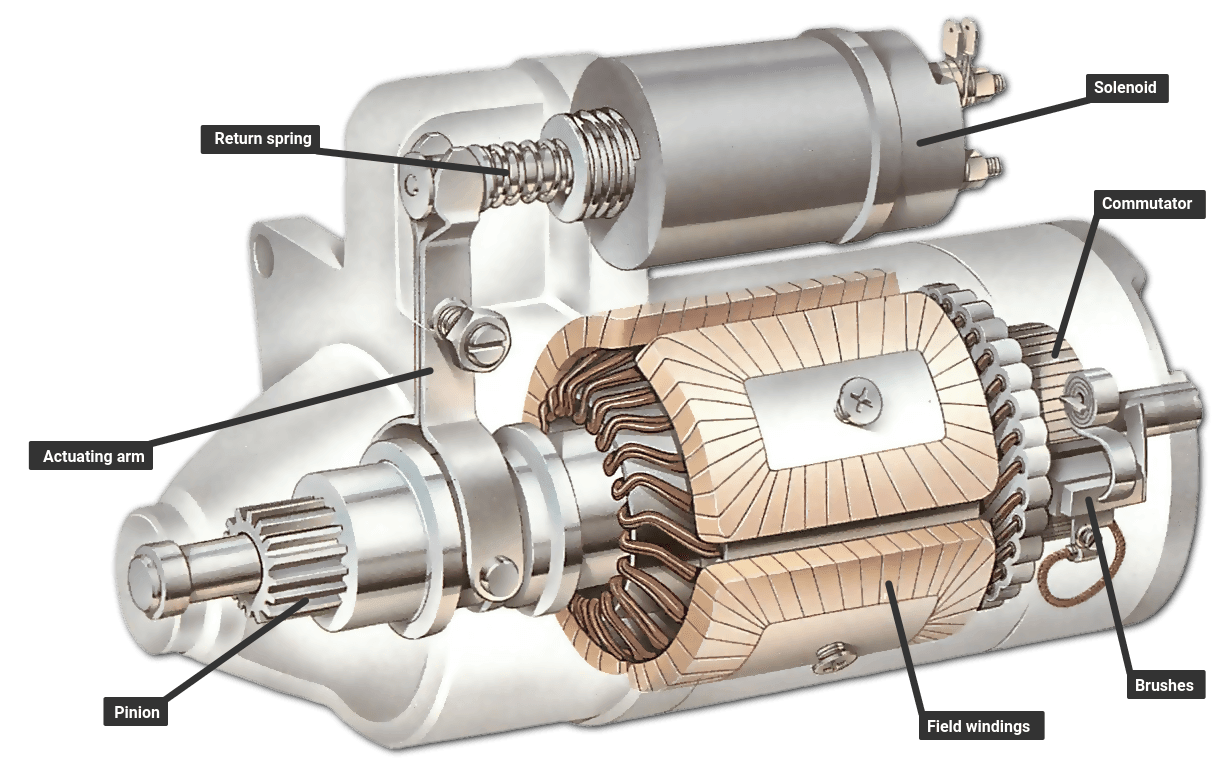
Web A Starter Motor Diagram Is A Visual Representation Of A Car’s Starter Motor Assembly, Outlining Various Parts Of Starting System Including The Starter Wiring, And Starter Control Circuit.
Web just an idea on how a starter motor is wired up and how to bench test itmy other channel shed floor build: The “b” or “battery” terminal: The starting motor is mounted on the engine flywheel housing.
The Solenoid Uses Electrical Current From The Battery To Close The Circuit And Engage The Starter Motor.
Web to begin with, a starter motor wiring diagram consists of several components including the motor, wires, connectors, and solenoids. The terminal that connects the cable to the starter motor.

Direct Online Starter Wiring Diagram « Electrical and Electronic Free

Basic PLC program for control of a threephase AC motor

Triaging a nocrank condition and testing a starter motor Hagerty Media

Direct Online Starter (DOL Motor Starter) Circuit Diagram and Working

Direct Online Starter Animation Diagrams

247 AUTOHOLIC TechSpec Thursday GM Starter Wiring

Electrical Page D.O.L Starter Motor Wiring Diagram (Star Delta)
Engine Starter Motor Diagram Wiring Diagram Schemas
