Simple Buzzer Circuit Diagram
Next, place the buzzer right beside the wire facing horizontally. This is a result of the induced rapid movements created in.
Piezo Buzzer Circuit Diagram Wiring Diagram
Simple Buzzer Circuit Diagram. However, from the experiments, this value will be the best frequency. It simply involves making a ring circuit that creates a series of general bell sounds. Web buzzer circuit diagram, simple buzzer circuit diagram and connection using ic 555, list of component required, connection procedure, working principle
Web Buzzer Circuit Diagram, Simple Buzzer Circuit Diagram And Connection Using Ic 555, List Of Component Required, Connection Procedure, Working Principle
Here’s a circuit diagram to help you understand better: It only uses a relay in series with a small audio transformer and speaker. All the voltages referred to here are d.c.
One Led And A Buzzer Is Connected To Pin3 Of 555 Timer With A Resistance Of 150 Ohm.
Web a basic schematic diagram of a simple buzzer is relatively easy to understand. Which can change slightly the value of both components, so the output sound changed. A buzzer circuit diagram shows how electric current is controlled through a series of switches by an electromagnetic coil.
The Heart Of This Circuit Is Formed By Ic1, A Tda2030.
Prior to reading a schematic, get familiar and understand all. Here no external oscillator is required to drive the piezo, rather the circuit is a self. The relay will operate via the transformer primary and closed relay contact, when the switch is pressed.
Sound, The Other Type Is Called A Readymade Buzzer Which Will Look Bulkier Than This And Will Produce A Beep.
However, from the experiments, this value will be the best frequency. When a voltage is applied across the two electrodes, the piezoelectric material mechanically deforms due to the applied voltage. Arduinos such as the arduino uno operate from 5v.
Connect The Black Wire From The Negative To The Board.
Buy from amazon hardware components the following components are required to make buzzer circuit ne555 ic pinout This is a result of the induced rapid movements created in. The buzzer may operate at 9v, 12v or some other voltage.
Web A Buzzer Is Understood As A Device That Creates An Audible Tone Under The Influence Of An Applied External Voltage.
A buzzer is a high frequency oscillator circuit used for generating a buzzing sound through a transducer or speaker output. Web this circuit is a simple buzzer circuit and it called novel buzzer. Web the circuit description given below will surely help you to understand better regarding how to make a buzzer:
Web Hi , This Video Is To Show You How To Make A Simple Beeping Buzzer Circuit, Which Can Be Used As Alarm.
Web in this article we learn how to make a very simple circuit for buzzer using piezo electric transducer, two resistors, a small coil and a bc547 transistor. Web here is a simple water level buzzer circuit which can be used to detect or sense the level of water in tank, pool, washing machines etc. It simply involves making a ring circuit that creates a series of general bell sounds.
The Circuit Mentioned Below Will Produce A Buzzer Sound When 9 Volt Power Will Be Applied.
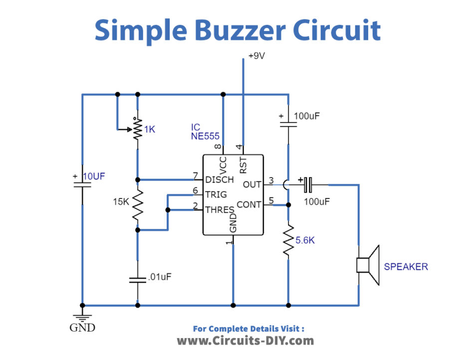
R1 and r2 apply a voltage equal to half the supply. Ne555 is a timer ic comes in 8 pin dip package, it performs wide variety of tasks in electronic circuits. At its core, it consists of a power source, a resistor, an electromagnet, and a diaphragm.
Sound Due To The Internal Oscillating Circuit Present Inside It.
This electric current is then used to activate the buzzer, creating sound. Web a powerful buzzer in the room, combined with a pushbutton at the bottom of the stairs or in the kitchen, could be very handy in such situations. Web piezoelectric as the name suggests, the piezoelectric type uses the piezoelectric ceramic’s piezoelectric effect & pulse current to make the metal plate vibrate & generate sound.
Web Check Out Wiring Diagrams From Negative To Positive And Redraw The Circuit As A Straight Line.
This is a project of a 555 buzzer circuit. This output may either be in the form of a buzzing or a beeping sound. Web the one shown here is a simple buzzer which when powered will make a continuous beeeeeeppp.
The Best Part Is, You Can Use Transistors To Make An Easy And Cheap Buzzer Circuit.
Pin6 is also connected to pin7 with a 10kohm variable resistance. When connected to the power source, current is applied to the electromagnet and this creates a vibrating effect on the diaphragm which in turn produces the sound of a buzzer. Web this article and circuit diagram show how to connect a buzzer to an arduino when the buzzer operates at a different voltage to the arduino.
Web Simple Buzzer Circuit Diagram.
It has different applications in offices, schools, quiz competitions, sports, and games. Next, place the buzzer right beside the wire facing horizontally. Pin2 is connected to pin6 and a capacitor (here we used 4.7microf) is connected with pin2 & ground.
Web Adding Loudness To Your Buzzer Circuit Is Not A Complex Process.
When the two probes shown in this water level indicator circuit will detect water the buzzer will start producing sound. Web a buzzer circuit diagram is simply a visual representation of how a buzzer operates within an electrical system. Web piezo buzzers are constructed by placing electrical contacts on the two faces of a disk of piezoelectric material and then supporting the disk at the edges in an enclosure.
Web Buzzer Circuit | Circuit Diagram.
The circuit is very simple and low cost using.

How to Make a Homemade Buzzer? Simple Circuit Design Explored

How to Make buzzer circuit projects in 2021 Circuit

How To Make A Simple Circuit Without Switch Wiring Diagram

Simple Buzzer Circuit with NE555 IC

Hobby Electronic Circuits Simple Piezo Buzzer Circuit

How to Make buzzer circuit projects Circuit

Simple Buzzer Circuit stock vector. Illustration of diagram 232574616
Piezo Buzzer Circuit Diagram Wiring Diagram
